Brushless Motor Controller Data
Sensorless controllers for permanent magnet motors such as IntegratedThrusters™.
This type of motor requires an electronic controller. We offer two families of controllers - adjustable speed and servo.
What is sensorless control?
You may be familiar with brush DC motors. Connect a DC supply to the motor, vary the voltage and the speed will vary accordingly.
This simplicity comes at a price - the brushes that need replacing when they start sparking and the limited power because the winding is on the shaft, with limited cooling.
The brushes are part of the essential commutation process, where the polarity of the voltage applied to the armature winding is reversed in step - synchronously - with rotation.
In brushless DC motors like ours the winding is on the outer fixed stator and the propeller rotor carries magnets - it can produce high power because the rotor does not get hot and it is extremely reliable because there are no brushes. But, the DC power supply has to be synchronously commutated by an electronic controller.
A simple way to guide the electronics to synchronism is to fit shaft rotation sensors. Unfortunately these are unreliable, expensive to fit and require further waterproof connections.
TSL Technology has been successful in applying proprietary sensorless control to thruster applications. As its name suggests, the technique requires inferring the shaft position from the power connections alone. Our controllers achieve 100:1 thrust ratios, ample for most applications.
Adjustable speed controllers, as the name implies, are ideal for applications which need simple on/off, forward/reverse operation and limited rate of change of speed. AUVs and some ROVs fall into this category.
Servo controllers are designed for rapid slewing of speed including sweeping from forward to reverse. They include stall detection and auto restart. You need to understand that a rapidly slowing motor, including throwing into opposite thrust, means the thruster is absorbing a lot of energy, and this has to go somewhere. If your power supply cannot absorb the energy then a supply line absorber (electronic brake) is required. Conversely if you accelerate very rapidly there is a noticeable dynamic power requirement for accelerating the rotor inertia, and this may call for a larger controller than steady speed operation would need.
Here are the ways to kill any controller, in order of rapidity: overvoltage (instantaneous); short-circuit (seconds); inadequate cooling (minutes). Make sure your supply voltage is well defined, check your connections carefully, and make sure the controller is ventilated or thermally connected to a heatsink.
It is possible to run the controllers in dielectric fluid, even pressurised. Fluids you can try include HFE-7100 and transformer oil. We do not however warrant controllers operated in this way.
Standard controllers operate 18 - 30VDC for a nominal 24VDC thruster. Lower voltage will limit attainable power. This is because thrust varies as propeller speed squared, maximum speed varies as supply voltage.
The THR series controllers include a port for motors with sensors. In extreme applications like servoing at negligible thrust or violent slewing sensors may be necessary.
Please enquire for controllers for higher and lower voltage and/or power.
|
 |
6 x 250W multi-channel servo controller 133 x 203 x 22mm RS232 or RS485 interface |
|
 |
4 x 1.5kW multi-channel servo controller with 2 expander channels 133 x 203 x 22mm RS232 or RS485 interface |
|
 |
1 x 15kW expansion controller 85 x 160 x 45mm Hosted by PA-THR-0502 |
|
 |
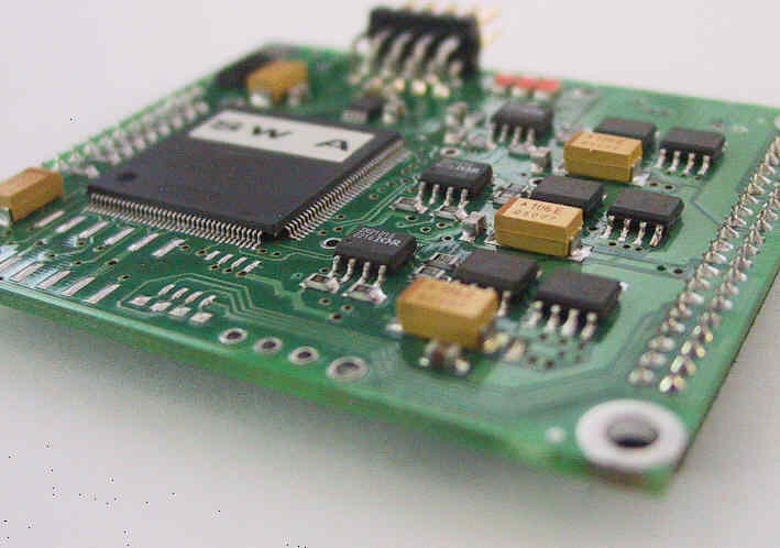
100W adjustable speed controller; 140W with cooling. 60 x 50mm piggy-back mount Parallel interface |
|
 |
2 x 250W multi-channel servo controller 133 x 95 x 30mm RS232 or RS485 interface |
Data has been carefully checked and is believed reliable but does not form part of any contract. TSL Technology reserves the right to make product changes without notice.
